Blog - BMS Systems

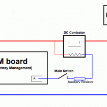
SBM wiring diagram with charger and controller
SBM wiring diagram with charger and controller
Please note that the main switch must be turn off, when the equipment will not be used. Otherwise the DC coil of the DC-contactor will always drain the battery.
The auxiliary resistor (at the DC contactor) is needed only in case the voltage of the coil of the DC contactor does not match (is lower than) the voltage of the battery pack. (Example: you have a 36V battery pack and you wish to use a 24V DC contactor or even just a 12V DC contactor - the resistor prevents from the burning of the coil when using with a higher voltage.)
Note: we also recommend using the reverse diode to protect the SBM when using the DC contactors.

 English
 Česká republika
 Germany
 France
 España
 Italia
 Sverige
 Polski
 Nederland


